EMG Circuit Design
BOM:
1 Instrumentation amp
4 op amps
Electrodes
Alligator clips
Some capacitors
Some resistors
A diode
A zener diode
Coffee
Steps:
0. Drink coffee
1. The signal from two electrodes is amplified by an instrumentation amp.
2. The instrumentation amp uses a right leg drive for setting a reference.
3. The signal from the instrumentation amp is filtered in a band pass filter passing 20-400 Hz.
4. The signal is amplified and filtered more with op amps.
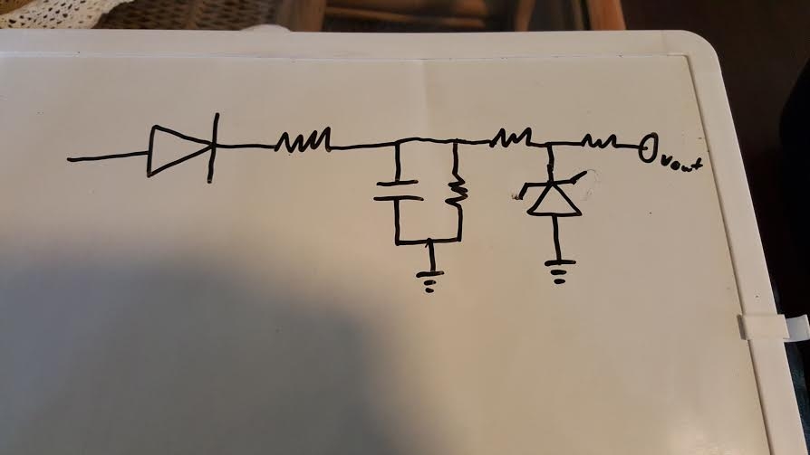
5. The signal is then rectified with a diode.
6. Finally the signal is clipped at 5V for micro-controller safety.
Step 0.

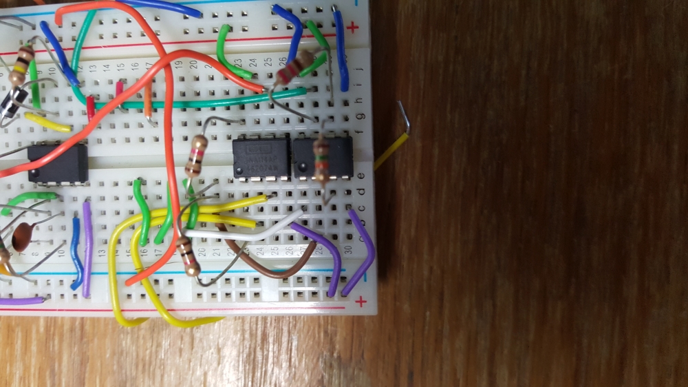
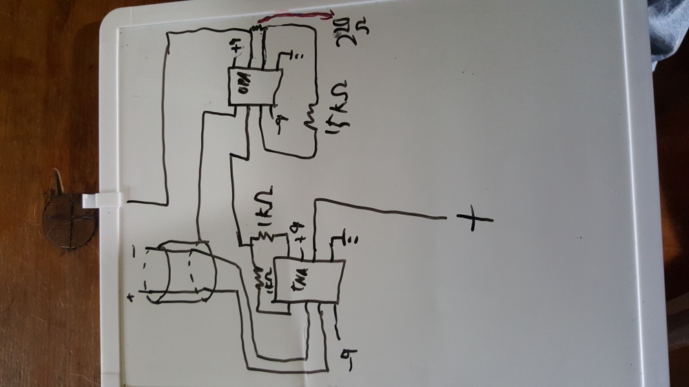
Step 1 & 2.
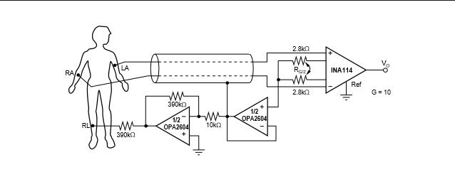
The cylinder around the electrodes is shielding, we don't have shielded wire, just wrap a wire around your other wires and connect to that.
Step 3:
Filter out high and low frequency noise from your signal. Ideally keep 20-400 hz

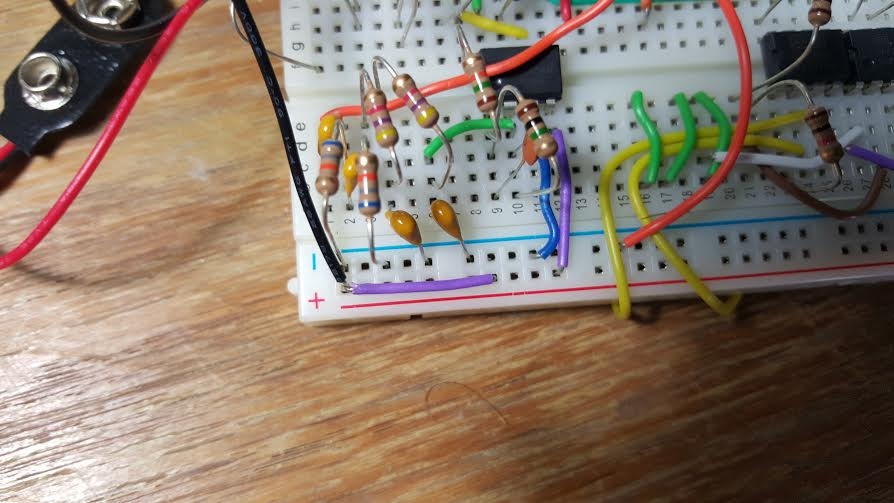
The four resistors and capacitors seen in the bottom left corner pass about 22-330 hz. Good enough for me, no need to go crazy with resistors to get exact cut off points.
Step 4
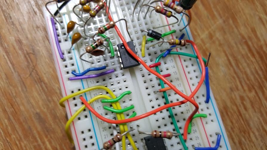
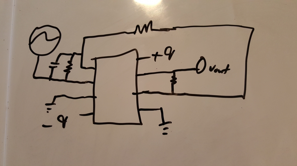
Now we need to bring the signal up near 5 volts, use two more op amps to amplify it. While amplifying the signal I do additional filtering by adding a capacitor in a feedback look to make an integrator.
Step 5 &6 :
Rectify your signal and smooth it out to make it easy for a micro-controller to interpret, and clip it at 5v to make it safe for the micro-controller. Some micro-controllers use 3V, check yours or just do 3V to be safe.
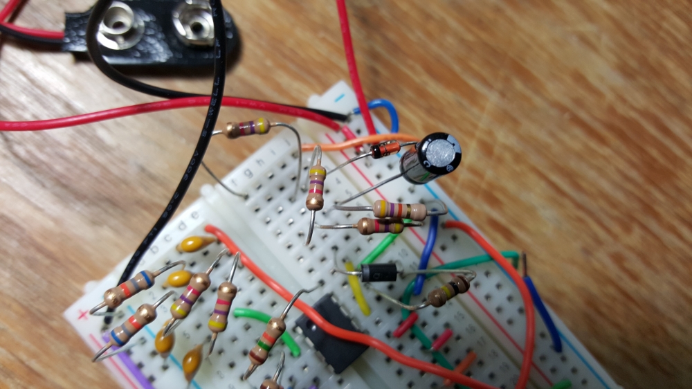
This should give you a working EMG.
Your circuit may be different than mine.
You may want to omit the passive bandpass filter and make an active one using an op amp. You may want to increase or decrease the gain or try other versions of the right-leg drive. You may need more or less gain depending on the muscle group that interest you in order to get the best resolution for that application. I did not include the values of components on the schematic because I don't expect you to copy it. This is a reference point for you to design and build your own. While you can figure out the values easily by looking at the photos, that is not my expectation.
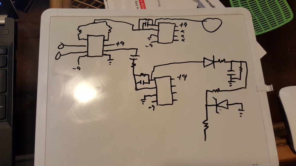
As an example here is alternative simpler circuit that would only require 2 op amps. I never tested or made this one, but it should work.
Here is a previously made EMG circuit that is similar, but still slightly different.
http://letsmaketech.com/index.php?controller=post&action=view&id_post=8
Try some things out see what works best for you.
If you need feel free to email me at the email address provided in class.
